Abstract Carbon fiber composites (CFRP) are widely used in aerospace, defense military, automotive aircraft components and other fields due to their high strength, high modulus, low density, high temperature resistance, corrosion resistance, friction and fatigue resistance. Take the Airbus A380 as an example, carbon fiber complex...
Carbon fiber composite (CFRP) is widely used in aerospace, defense military, automotive aircraft components and other fields due to its high strength, high modulus, low density, high temperature resistance, corrosion resistance, friction resistance and fatigue resistance. Taking the Airbus A380 as an example, the amount of carbon fiber composite material has reached 32t, accounting for 15% of the total organization. Together with other types of composite materials, it is estimated that the total amount can reach about 25% of the total weight of the structure. Drilling is one of the most common secondary processing methods for carbon fiber composites. The holes are mainly used for riveting or fastening structural parts. However, carbon fiber composites are prone to delamination, burr and tear defects during drilling and hole making because of their anisotropy and non-uniformity, low interlayer bonding strength, and high temperature influence. Typical difficult to machine materials. Studies have shown that in the common pore defects of the above-mentioned several carbon fiber composites, the delamination defects have the greatest influence on the bearing capacity and fatigue strength of the composite structural members. In this paper, the current research status at home and abroad is reviewed from the aspects of the generation mechanism, influencing factors and detection of delamination defects in carbon fiber composite drilling process.
Mechanism analysis of CFRP Due to the particularity of CFRP mechanical properties and the diversity of internal structure, the deformation process of materials is much more complicated than metal materials in the cutting process, which is not only related to traditional factors such as tool shape and process parameters, but also Direct influence of fiber and matrix properties and fiber layup direction. Therefore, the cutting mechanism of CFRP is very different from the traditional metal cutting mechanism.
1. Cutting mechanism of CFRP In 1983, Koplev et al. conducted an experimental study on carbon fiber cutting process earlier, pointing out that CFRP chips are mainly formed by brittle fracture of materials. DHWang et al. performed orthogonal cutting tests on unidirectional and multi-directional carbon fiber composites, and studied the effects of different fiber directions on chip formation mechanism. Since the carbon fiber composite material consists of brittle carbon fiber and a tough resin matrix, the strength limits of the two are very different. The former is several times larger than the latter. Therefore, scholar Zhang et al. believe that it can be simplified as a carbon fiber only during the cutting process. The cutting will be ignored for the cutting of the resin matrix.
The literature studies some typical fiber layup directions and summarizes the formation of chips in carbon fiber composites at different fiber orientation angles θ (see Figure 1).
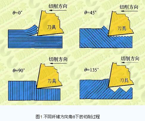
When 0°<θ≤90°, represented by θ=45° and θ=90° in Fig. 1, the pushing action of the cutting edge on the carbon fiber composite material forms a shear stress perpendicular to the fiber's own axis inside the fiber. . When the shear stress exceeds the fiber shear strength limit, the fiber is cut. The cut fiber is slipped in the direction of the fiber under the pushing action of the rake face of the tool. When the shear stress between the fiber interfaces caused by the slip exceeds the shear strength limit of the matrix resin material, the cut fibers are separated from the other fibers to form chips. This form of cutting deformation is called a fiber cut type.
When 90° < θ < 180°, represented by θ = 45° in Fig. 1, the pushing action of the tool on the front end material results in interlayer separation between the composite materials. The tool front material is bent under the action of the tool, and the bottom breaks when the bending stress exceeds the bending strength limit of the carbon fiber composite. As the tool continues to advance, the tool pushes the material at its front end to strengthen. When the shear stress at the breaking point of the bottom of the material exceeds the limit of the material shear strength, shear fracture occurs and chips are formed. This form of cutting deformation is called a bending shear type.
2. Layering mechanism analysis Layering refers to the phenomenon of degumming separation and destruction between composite layers caused by interlayer stress or manufacturing defects. Studies have shown that delamination defects in the drilling of carbon fiber composites can be divided into two damage mechanisms: inlet stripping stratification and outlet ejector stratification (see Figure 2).
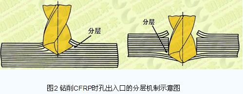
For the mechanism of stratification, Zhang Houjiang et al. pointed out through acoustic microscopy that the inlet and outlet sides of the CFRP plate drilling hole are layered, the inlet side layer is circular, and the outlet side surface layer is oval, deep layered. It is a ring shape; the stratification on the outlet side of the same hole is much larger than the delamination on the inlet side.
1. Cutting parameters affecting cutting parameters Variables mainly include cutting speed, feed rate f (feed per tooth fz) and other factors. Cutting speed and feed rate are the two main parameter variables in the drilling process. Studies have shown that the effect of feed on layered defects is greater than the cutting speed. António T. Marques et al. used four different drill bits to study the cutting performance under different cutting parameters. Tests have shown that reasonable selection of cutting parameters can reduce axial forces and thus reduce the effects of delamination defects. The experimental study indicated that cutting the material at a feed rate of 0.025 mm/r and a cutting speed of 53 m/min can minimize the axial force and stratification factor, and the stratification factor decreases by about 4%-5%.
VNGaitonde et al. used a cemented carbide drill bit (K20) to conduct a drilling test on carbon fiber composites. The results show that the stratification trend decreases with increasing cutting speed, and the low feed rate and apex angle can reduce the delamination. factor.
When Zhang Houjiang used the YG6X solid carbide four-faced drill to drill CFRP, it was found that the effect of feed rate on the delamination of each layer was concave. When the feed rate is small, the feed amount is increased and the layer size is decreased; when the feed amount is exceeded, the feed amount is increased, and the layer size between the layers is increased. Therefore, it is the feed amount that produces the smallest stratification, which is a critical value.
Vijayan Krishnaraj et al. studied the cutting performance of carbon fiber composites with K20 carbide drills at different spindle speeds and feed rates. Tests have shown that there is no obvious rule between the inlet side peeling stratification factor and the feed rate, but overall, the low feed rate stratification factor is smaller than the high feed rate stratification factor. The exit side ejection stratification factor increases as the feed rate and spindle speed increase. The feed rate is the main influencing factor of the outlet side leaching factor. The contribution rate of the feed rate is 51.4%, and the contribution rate of the spindle speed is 35.42%. The test also gave the optimum feed rate and spindle speed of 0.137 mm/r and 12000 r/min, respectively.
2. Influence of the tool Since the carbon fiber composite material is a typical difficult-to-machine material, and the drilling process is a semi-closed process, a large amount of heat generated during the cutting process is not easily taken away by the chips and the tool. Therefore, the drilling process is liable to cause wear of the tool. The wear of the tool not only affects the quality of the hole but also affects the hole making efficiency and increases the processing cost. The factors affecting the tool mainly include tool geometry, tool coating, tool parameters and so on.
Since the critical axial force causing the delamination defect is affected by the cutting edge, the tool geometry plays an important role in reducing the delamination defect. LuÃs Miguel P.Dur?o et al. studied five types of tools: 120° top angle twist drill, 85° top angle twist drill, sawtooth drill, dagger drill, step drill. The research shows that the stratification factor of the 120° apex twist drill is the smallest, the stratification factor of the step drill is second, and the stratification factor of the 120° apex twist drill is not much different. The largest stratification factor is the sawtooth drill, which is about 1.23. Therefore, the tool with the best test conditions is a 120° apex twist drill, followed by a step drill.
For carbide coated tools, there are mainly common types of coatings (such as AlTiN) and diamond coatings. Xin Wang et al. studied three different tools: uncoated carbide drills, diamond coated carbide drills and AlTiN coated carbide drills. The test results show that the diamond coating can significantly reduce the wear of the tool, however, the AlTiN coated cemented carbide drill bit fails to effectively reduce the tool wear rate due to oxidation during the drilling process. Redouane Zitoune and others use a nano-coated carbide drill to drill carbon fiber and aluminum alloy laminates. They pointed out that the use of nano-coated carbide drills can significantly reduce roughness and axial forces during drilling CFRP. The reduction in axial force can effectively prevent delamination defects during drilling.
3. Other influencing factors have many factors affecting delamination defects. In addition to the above-mentioned extensive research on cutting parameters and tools, there are other important influencing factors, such as the pre-impregnation method of materials, the influence of guide holes, the influence of the shims, and the new process. Wait. Islam Shyha et al. compared the effects of three types of prepreg materials (977-2/HTS AC, 8552/AS4 AC, MTM44-1/HTS OC) on the drilling process. Studies have shown that the pre-impregnation method contributes 12% to the delamination defect on the inlet side; however, the leaching defect on the outlet side has a contribution rate of 38.5%. In addition, the grading factor of the 8552/AS4 AC prepreg is large, especially at high feed rates (0.4 mm/r). CCTsao and H. Hocheng studied the effect of pilot holes on layered defects, where the diameter of the pilot holes is equal to the inner diameter of the nest drill. The test results show that although the critical critical axial force is reduced by the guide hole, the axial force during the drilling process is also greatly reduced due to the removal of the chip. By controlling the ratio of the diameter of the pre-guided hole to the diameter of the borehole, the carbon fiber composite can be drilled at a large feed without delamination defects. CCTsao and H. Hocheng studied the effect of layering defects by installing a backing plate at the bottom of the material being processed. They first derived the stratified critical axial force model formula for sawtooth drilling and nesting drilling with padding, and then carried out experimental verification. Studies have shown that mounting pads can achieve better drilling quality than without mounting pads.
In recent years, based on a large number of researches on the mechanism of drilling and hole making, researchers have tested some new methods of hole making and material processing, and achieved certain results. This paper takes spiral milling and hole making technology as an example. The spiral milling and hole making technology is a new cutting method for making holes by using the milling principle. In the spiral milling process, different apertures are obtained by changing the eccentricity of the tool and the hole axis. Therefore, the same tool can be used for the hole making and the armpit processing of different apertures, thereby reducing the processing cost and improving the processing efficiency. Wang Ben et al. used the traditional drilling process as the reference, and used the spiral milling and traditional drilling methods to make the hole making test of the C/E composite material, and analyzed the trajectory of the spiral milling and the traditional drilling tool. The results show that the cutting temperature is an important factor affecting the quality of C/E composites. Because the cutting temperature during spiral milling is lower than the traditional drilling by more than 69 °C, the reduction is more than 36%, so the tearing and delamination at the outlet of the hole is effectively avoided.
The stitching technique is a method for enhancing the effective joint reinforcement of a composite liquid-formed preform. The principle is that the composite material is reinforced in a direction perpendicular to the plane of the layup by means of stitching, thereby improving the damage tolerance between the layers of the material. The interlaminar properties of the composite can be greatly improved by passing through the stitches in the direction of the thickness of the reinforcing fabric. Yosra Turki et al. studied the drilling performance of stitched and unstitched composites. The results show that the suture material has a significant improvement in surface quality and defect reduction compared to the unstitched material. The sutures create a compressive effect between the layers and hinder their separation during advancement of the drill bit. Therefore, the stitching technique can reduce delamination defects and matrix rupture caused by axial forces. KTTan et al. also studied the effects of stitch density and suture thickness on the failure mode and failure characteristics of carbon fiber composites.
In order to avoid artificial damage to materials, non-destructive testing technology has been widely used in the detection of delamination defects. The non-destructive testing technologies currently used mainly include acoustic microscopy, ultrasonic C-scan, X-ray computed tomography, and enhanced radiography. Zhou Zhengqian and others based on laser ultrasonic technology, quantitative characterization test of composite material fastening hole layering; laser ultrasonic C-scan detection based on penetration method and pulse reflection method, the shape, size and position of layered defects in fastening hole area were obtained. feature. The research results show that the non-contact excitation, reception and high resolution characteristics of laser ultrasonic technology can accurately measure the wave reflection and attenuation caused by the layered defects in the fastening hole area, and effectively characterize the fastening hole of the aircraft composite structure. Layer defects.
CCTsao and H. Hocheng use two non-destructive testing techniques, X-ray computed tomography and ultrasonic C-scan, to detect layered defects. The test results show that the results measured by X-ray computed tomography and ultrasonic C-scan technology are very close, both of which can reveal the critical axial force of different tool stratification. However, X-ray computed tomography is more flexible and effective for detecting layered defects.
Conclusion With the increasingly high performance requirements of carbon fiber composites and increasingly harsh working conditions, the quality requirements for carbon fiber composites are also increasing. Layering is one of the main defects in the drilling and hole making process. Domestic and foreign scholars have conducted in-depth research on its mechanism and influencing factors. Optimizing the rational selection of cutting parameters and the use of different geometries and coatings is an effective way to reduce delamination defects. Through reviewing the research status of delamination defects of carbon fiber composites at home and abroad, we can increase the research on the delamination defects of carbon fiber composites from the following aspects: continue to study new tools and optimize tool geometry parameters to improve its Cutting performance; in-depth study of composite materials, improve manufacturing processes, improve material properties; establish a sound and reasonable simulation model to achieve more accurate prediction of layered defects.
Abs Rod sold by AHD,it's quality has been rigorously screened, with light weight, good chemical resistance, long service life, good heat preservation, smooth inner wall, no scale, no bacteria, low friction coefficient and small water flow resistance (flow rate can be increased by 30%) High impact strength, simple connection, etc.
|
Product |
Diameter(mm) |
Length(mm) |
Color |
Density(g/cm³) |
|
20-200 |
2000 |
Nature |
1.06 |
ABS Rod
Abs Plastic Rod,Natural Abs Plastic Rod,Abs Rod ,Abs Plastic Bar
Shenzhen Anheda Plastic Products Co.,Ltd , https://www.ahdplastic.com