The gear hobbing is the same as the forming method to process the gear. When the gear is formed by the forming method, the tool is also used as a gear, and the gear is driven according to the speed ratio required by the meshing relationship, so that the tooth shape is cut out by the envelope. Unlike hobbing, the shaper must be moved up and down in addition to the meshing relationship (see Figure 1). The advantage of the exhibition method is that a tool can process various gears with the same modulus, tooth angle and different number of teeth. The hobbing can only process the external gear, and the gear can process the external gear and the internal gear, and can also process the stepped gear block, the herringbone gear and some gears.
Fig.1 Gear shaping and gear tooth profile rolling and forming
Tooth insertion process
The gear shaping motion is as follows: 1 The reciprocating motion of the gear shaping cutter is the cutting motion. The average velocity v is the cutting speed. The relationship between v and the stroke length L and the number of reciprocating times per minute is: v=2nL/1 000(m/min) . 2 The shape of the rotary cutter is selected according to the speed of the gear meshing relationship, that is, the size of the circumferential feed amount. 3 The gear to be machined shall be at the selected turning speed of the gear meshing relationship. 4 The radial feed of the pinion cutter can be used to cut out the full tooth depth one by one. 5 Let the knife move. When the gear cutter returns, the center between the knife and the blank is instantaneously enlarged to avoid the two. Due to the lost motion of the tool and the more complex movements, the production efficiency is lower than that of the hobbing (see Figure 2).
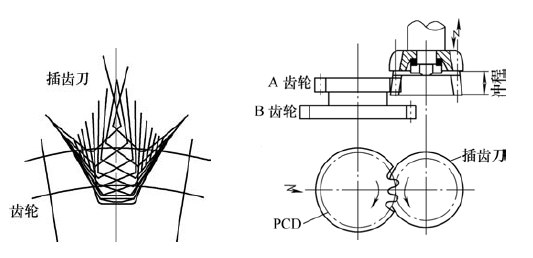
Figure 2 How the gear shaping machine works
(1) Insert straight teeth and helical teeth. When inserting straight teeth, use a straight-toothed cutter to make vertical vertical reciprocating motion. When inserting the helical gear, it is necessary to use a helical toothed cutter to reciprocate obliquely upwards and downwards through the spiral guide on the spindle of the gear shaping machine. In order to perform cutting, the top edge and the side edge of the shaper blade must also have a rake angle, a back angle, and the like. The shaper blade has three main structural forms, namely a disk shape, a bowl shape and a handle shape. The disc shape is used to machine the external gear, the step gear block and the larger diameter internal gear. The bowl shape is used to process the stepped gear and the internal gear with larger diameter. The difference between the structure and the disc shape is that the concave hole in the middle of the cutter body is deep to accommodate the fastening nut, so as to avoid hitting the workpiece when machining the step gear. . The handle shape is mainly used for the processing of small internal gears.
(2) Insert the internal gear. The ability to machine internal gears is a prominent feature of gear shaping.
However, the internal gear machining is more likely to cause interference than the external gear machining, so that the range of the internal gear machining and the design of the gear shaping cutter for machining the internal gear are limited. When cutting the internal gear, there are three kinds of interferences that can be generated: 1 Involute interference, which is generated when the number of teeth of the internal gear and the shaper blade is large, and the tooth tip of the internal gear can often be cut off. 2 Interference caused when the knife is retracted. When the difference between the number of teeth of the internal gear and the shaping cutter is small, the corner of the internal gear tooth tip is easily cut off when the shaping cutter is cut in and returned. 3 Cycloid interference, this interference occurs when there is less difference in the number of teeth compared to the interference when the knife is retracted. After the involute toothed bread is finished, the tooth tip of the tool will cut off some internal gear tooth faces; if the interference caused by the retracting knife is not generated, the trochoidal interference will not occur. Therefore, there is a limit in the design of the number of teeth of the gear shaping cutter. How to choose the number of gear teeth that can properly avoid interference according to the number of teeth of the internal gear, the tooth type (standard type and short tooth type) and the pressure angle. For details, refer to Figure 3. In Fig. 3, Zg and Zc respectively indicate the number of teeth of the workpiece and the tool, and the Zg and Zc teeth in the range of the hatching do not interfere with each other, and α p represents the pressure angle.
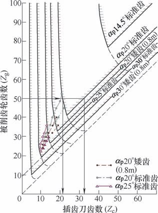
Figure 3 The number of teeth of the machined internal gear shaping cutter is selected
Generally, when the normal pressure angle is 20° and the number of internal gear teeth is 50, the number of teeth of the pinion cutter Zc is 22 ≤ Zc ≤ 32, and no interference occurs.
(3) Selection of main parameters. Modulus and pressure angle: The normal and normal pressure angles of the shaper must match the gear being machined.
Helix angle: The helix angle on the pitch circle of the pinion cutter must be the same as that of the gear being machined.
Number of teeth: The number of teeth of the pinion cutter is limited by the spiral guide when the helical gear is inserted. There are also restrictions when inserting internal gears.
When machining helical gears, the helix angle on the pitch circle of the gear shaping cutter should be equal to the helix angle of the helical gear being machined. The number of teeth should be calculated as follows: Z = Lsinβ 0 / πm n (1) where mn is the normal modulus of the gear; Z is the number of teeth of the gear; β 0 is the helix angle of the pitch circle; L is the guide of the spiral guide Cheng (mm).
Helical guide (see Fig. 4): The oblique insertion movement of the spur gear is dependent on the spiral guide, the lead L of the spiral guide, and its calculation formula is L=πD 0 /tanβ 0=πm n Z/sinβ 0(2 In the formula, D0 is the pitch circle diameter (mm).
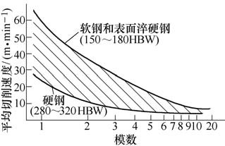
Figure 4 Schematic diagram of the helical guide of the gear shaping machine
It can be seen that when the same helical gear is machined with a different number of teeth, it is inevitable that the pitch and the helix angle are different, but they should be processed by spiral guides with different pitches. The same guide rail must produce machining error, such as the normal modulus is 2.5, the pressure angle is 20°, the helix angle is 20°, and both are right-handed. Use a 30-tooth cutter to substitute the formula (2). ), the lead of the guide rail should be 688.905mm; and the lead cutter of 50 teeth should have a lead of 1 148.175mm. If a guide rail is shared, the helical angle error of the machined gear on the pitch circle and the base circle can be caused.
(4) Determination of the amount of insertion. When the gear is inserted, the reciprocating motion of the gear shaping cutter is the main cutting motion, and its speed is the cutting speed. In addition, the engagement of the shaper blade and the workpiece gear in a certain speed ratio constitutes a circumferential feed motion. Mitsubishi Materials Corporation has recommended a cutting speed selection map for a cast steel gear (see Figure 5) for reference. It is based on a cutting length of 25 mm.
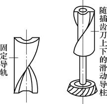
Figure 5 Selected cutting diagram of the average cutting speed of the gear teeth
(5) Precautions during processing. When the workpiece and the shaper are machined on the gear shaping machine, their oscillation should be controlled below 5μm, otherwise the step of the machined tooth surface will be caused.
The up and down reciprocating stroke of the pinion cutter should be selected according to the thickness of the gear to be machined, and the amount of free space should be added by the tooth thickness.
When the gear shaping is performed, one tooth of the gear shaping cutter cuts out one tooth groove of the gear to be processed, so it is necessary to pay attention to the damage and abnormal wear of the tooth due to the impact.
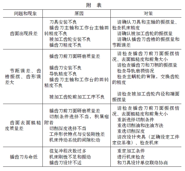
2. Problems and countermeasures in the processing of gear shaping
How to solve the problems and phenomena that occur during the processing of the gear shaping, the specific countermeasures are shown in the attached table.
Schedule
3. High performance, long life new shaper
The upper and lower reciprocating motion of the gear shaping cutter is subjected to impact load, and its toughness must be good. The high-speed steel used must also have good toughness. According to international standards, it should be HS6-5-2-5, China is W6Mo5Cr4V2Co5, the United States is M35, and Japan is SKH55. . To extend the life, the shaper knife can be coated. If life and performance are to be improved, the shape of the shaper must be changed to use a higher toughness powdered high speed steel and powdered high speed steel. Mitsubishi Materials has developed new powdered high speed steel materials KNA and KNAZ to meet these two requirements. In particular, KNAZ, which contains high alloy powders and unique fine high-hardness carbides, improves wear resistance, but its content should be appropriate, so that the toughness of the gear shaping cutter can be improved accordingly. Mitsubishi has also developed a special heat treatment technology that has a higher performance and longer life after processing.
The coated lancet has a much longer life than the uncoated one. In the past, TiN coatings were used in many cases. Mitsubishi Materials also developed an (Al,Ti)N purple coating. Its film hardness reached 2 700-2 900 HV (TiN was 1 800-2 000 HV), and the initial oxidation temperature reached 800 ~. 900 ° C (TiN is 600 ~ 700 ° C).
High Resistance Alloy is used to produce resistance elementof conductive material.Requirements including High mechanical strength, good corrosion resistance and oxidation resistance. Working temperature is usually at500 ℃. Commonly used with constantan chromium iron, iron chromium aluminum, nickel chromium, nickel, resistivity rho (20 ℃) is 1 Ω was/m or so. It is not used in the conduction of current, but with its high resistance to limit or control the current in the circuit, such as motor, potentiometer, standard resistors, potentiometers, slip line resistor resistance element and resistance line, etc.; For the using of high resistance in the pressure sensor,Temperature compensator and temperature measuring resistor of resistance element to creatte reflect strain, temperature, magnetic field and parameters; High resistance alloy can also be used as heating elements in the manufacture of the resistance heating equipment, could be applied in current, voltage regulating and the winding of control components.
Resistance Electrothermal Alloy
Resistance Alloy,Corrosion Resistant Alloy,Resistance Electrothermal Alloy,Fecral Resistance Heating Alloys
Jiangsu nickel alloy Co.,Ltd , https://www.xhalloy.com
