01 Introduction
The attenuation rate of components in photovoltaic power plants has been widely concerned by the industry. Beijing Jianheng Certification Center (CGC) has given some analysis on the evaluation method of the attenuation rate of photovoltaic modules.
02How to calculate the attenuation rate of photovoltaic modules?
The component attenuation rate refers to the ratio of the difference between the initial power of the component and the current maximum output power of the component and the initial power of the component, namely:

The key to calculating the attenuation rate lies in the measurement of the two parameters of the initial power of the module and the current maximum output power of the module.
03 Measurement of initial power of components
The initial power of the module is the maximum output power obtained from the factory test of the module, which is obtained by the solar simulator of the enterprise production line.
For the component production line, the main factors affecting the factory test are the following:
Ambient temperature: controlled by air conditioner at 25 ± 2 ℃
Test equipment: The level of the solar simulator is AAA
Calibration and standard components: Use the calibrated standard components to calibrate the solar simulator to correct the test results.
According to the research conducted by Jianheng CGC, there is a certain degree of uncertainty in the factory test of the production line, and its main influencing factor is the standard component.
If a more accurate test module initial power is required, the test can be carried out by a laboratory with strong capabilities and low uncertainty.
Uncertainty of measurement: characterize the dispersion of the values ​​reasonably given to the measured value, and the parameters associated with the measurement result mean the degree of suspicion or uncertainty about the reliability and validity of the measurement result. An interval derived from the assessment quantifies the quality of the measurement results.
04 The current maximum power test of the component
The current maximum output power of a component refers to the maximum output power measured by the component after a period of operation. Influencing factors such as dust shielding, component defects, etc. should generally be excluded, and the maximum output power of the component itself should be tested.
When testing the maximum output power of components outdoors, the main influencing factors are as follows:
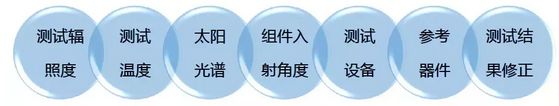
Test irradiance: linear devices should be tested at irradiance of not less than 800W / m2;
Test temperature: For the single glass component of the general backplane structure, the temperature of the backplane reflects the junction temperature of the battery;
Solar spectrum: different regions and environments will have different solar spectrums, which should be corrected with the spectral value of AM1.5 during accurate measurement;
Component incidence angle: different light angles affect the power generation performance of the component, and the impact of the incidence angle on the test results should be considered when measuring accurately;
Test equipment: handheld outdoor test equipment, which needs to be used together with irradiation test and temperature test equipment;
Reference device: usually a well-packaged WPVS;
Test result correction: The result of correcting outdoor irradiance and temperature to STC conditions according to the IEC60891 standard.
Affected by the above factors, the uncertainty of the maximum output power of the outdoor test component is slightly higher than the uncertainty of the production line test.
If you need a more accurate test of the current maximum output power of the component, it is a good choice to send the component to the laboratory for testing.
05Laboratory test
Laboratory testing can better control the test environment, test equipment, and reference devices, thus obtaining more accurate test results with lower uncertainty.
The main factors affecting laboratory testing are:

Ambient temperature: It is usually controlled within the range of 25 ± 0.5 ℃, and it should be as close as possible to 25.0 ℃ during the test to reduce the deviation caused by temperature correction.
Test environment: darkroom environment, minimize the impact of ambient light or light reflection on the test results.
Test equipment: The level of the solar simulator is required to be AAA (some can reach 3A +), and the test method is as close as possible to the characteristics of the sample under test (such as measuring high-capacity devices with long flash time).
Calibration and standard components: According to the requirements of IEC60904-4, the test results can be traced back to the national metrological benchmark.
The uncertainty of the maximum output power of laboratory test components is about 2% -3%.
The Jianheng Certification Center (CGC) led the capacity verification of two photovoltaic laboratory module tests in 2012 and 2015, respectively, and the evaluation results showed that there was a certain deviation in the maximum output power of the laboratory test. The deviation of results between most laboratories is about 1%. This deviation is mainly caused by the traceability difference of reference devices.
06 How to correctly assess component attenuation
Based on the above, the key point for the correct evaluation of the attenuation rate of the component is the temporal and spatial consistency of the test results.
Time consistency: At different test times (same test equipment), the test results of the same test object are consistent before and after;
Spatial consistency: At different test locations (different test equipment), the test results of the same object are consistent with each other.
For the measurement of the initial power of the component, not only the STC conditions must be met as far as possible during the factory test, but also the measurement traceability needs to be mastered. When necessary, the factory-made components can be sealed as reference components and sent to a third-party laboratory for testing, so as to eliminate test deviations caused by traceability during subsequent testing at different test locations (test equipment).
For the measurement of the current maximum output power of the components, the components without defects and dust should be screened and tested under STC conditions. The test conditions and traceability should be consistent with the initial power as much as possible to ensure the consistency of the test results and the initial test results.
07 On-site evaluation method of component attenuation rate

On-site component EL and appearance inspection: Randomly select components on site for appearance and EL inspection, and classify according to quality status.
On-site component power test: on the basis of appearance and EL test, three time points and irradiation intervals are selected for component IV testing, including three irradiation intervals of 400-600w / m², 600-800w / m², and 800-1000w / m². .
Return to factory test: select some components from the components tested on site, return to the manufacturer, and test the maximum output power in the production line and enterprise laboratory respectively (the third-party personnel witnessed on-site).
Third-party laboratory test: After the manufacturer completes the test, it is sent to a third-party laboratory for maximum output power test under STC conditions.
Cement-based non-shrinking self-leveling Grouting Material
KS series of grout is a high-tech one-component grouting material using Portland cement, pre-grade filler and additives that control the expansion in the plastic and can reduce water consumption.
Application of grouting Material:
Widely used in free-flowing precision grouting construction, including heavy machinery floor support, crane tracks and pillars foundation, but also can be used as mast, anchor bolt of the excellent reinforcement of grouting material; also is a good material for concrete repair works; design Beneath bridge supports, posts and flanged lamp posts, heavy pillar bases, and machine bases with dynamic loads. Such as thermal power plants, large paper mills, steel plant, steel mills, large machinery and equipment plants, cement plants.
Product advantages:
1, compensation shrinkage ---- gas expansion system, to compensate for shrinkage and settlement in the plastic slurry, to ensure that the grout material and the foundation in close contact
2, no chloride ---- The formula does not use chloride, thus avoiding the chloride hazards
3, high early strength ---- make the factory equipment faster to install and early use
4, non-ferrous ---- will not be rusty and stains or cracks due to rust expansion
5, reliability ---- factory pre-packaging materials, to eliminate the site produced by the error mixing
According to the standard:
KS series grouting material is based on the following part of the relevant standard test:
ASTMC-1107-97(Type)CRD-C621-82A
YB/T9261-1998 MS 522:part2:1989
ASTM C940-87 BS 4551:1980
JC/T986-2005
Expansion performance:
According to the American Standard ASTMC827 plasticizing stage test expansion rate of 0.5% or more, the long-term expansion of the curing stage to meet the requirements of the relevant standards.
Material properties:
|
project model |
KS-40 |
KS-60 |
KS-801 |
|||
|
40 |
401 |
60 |
601 |
|||
|
(mpa) compression strength(mpa) |
1 day |
20 |
22 |
25 |
30 |
45 |
|
28 day |
40 |
50 |
60 |
70 |
85 |
|
|
(mpa) Flexural strength(mpa) |
28 day |
9 |
10 |
12 |
12 |
12 |
|
Setting time |
Initial setting |
6.5h |
6.5h |
6h |
6h |
6h |
|
Final condensate
|
8h |
8h |
7.5h |
7.5h |
7.5h |
|
|
Expansion time |
Plastic stage |
Start 10min to initial setting |
Start 10min to initial setting |
Start 15min to initial setting |
Start 15min to initial setting |
Start 15min to initial setting |
|
Curing stage |
The final setting to cure more than 28 days |
The final setting to cure more than 28 days |
The final setting to cure more than 28 days |
The final setting to cure more than 28 days |
The final setting to cure more than 28 days |
|
|
Liquid density |
(kg/m³) |
2150 |
2150 |
2200 |
2200 |
2250 |
|
Water consumption |
Ks/dag |
3.8~4.0 |
3.8~4.0 |
3.8~4.0 |
3.8~4.0 |
3.6~3.8 |
1. floor grouting:
The flow distance should be determined based on the slit width and the liquid flow indenter to ensure that the grout flows from the gap to the front exit and the gap must not exceed 200 mm. If you guarantee a pressure head of 250mm, the maximum flow distance of up to 3 meters.
Note: The base surface must be constructed with oil-free and non-adherent loose material. If the surface of the concrete defects or slurry is cut intact before construction, the screw holes or solidified hole dust or sand blown net.
2. Floor:
Clean, no oil and other impurities must be removed to provide relief holes to ensure that all isolated areas are ventilated.
Pre-soaked: A few hours before grouting, the cleaned foundation must be submerged in water. Remove water from the free water and the hole just before pouring.
3. Stir:
To achieve the desired consistency, the amount of water must be accurate, the selected amount of water after slowly pouring it into the mixing vessel, while stirring feed, add complete package and continue stirring for 3-4 minutes until evenly dispersed, no knot Block phenomenon so far.
4. Grout:
The well-mixed material is poured over a period of 10 minutes to fully benefit from the expansion process. Each single perfusion thickness up to 200mm, the minimum width of the seam is 10mm.
5. Specific construction of large volume grouting:
Such as the thickness of more than 200mm. Aggregate grading (stones up to 10 mm in diameter) shall be added to the slurry to reduce the heat of hydration. The amount of aggregate used shall not exceed 1 part by weight of 1 part of KS series grout.
6.Low temperature construction:
When the temperature drops below 2 ° C, warm water (30-40 ° C) may be
used to accelerate the strength increase and the cementitious material
should be handled in winter.
High-temperature construction:
When the temperature exceeds 35 ℃, grouting material should be stored in a cool place, and cold water mixing.
Conservation:After grouting is complete, all exposed parts should be cured with Cask Cares or wet sacks.
Countermeasure :
KS series grout contains cement powder, which when mixed with gypsum or
when wet, releases alkali that is harmful to the skin. Avoid inhaling
dust and avoid touching the skin or eyes.
Estimation:pack
KS series grouting material) 25KG/bag
Under free flow the volume is about 13.0L
CONSTRUCTION schematic:


Storage:
KS series grouting material intact material in dry place storage period
of 12 months, if stored in high temperature and high temperature
storage area will be shortened.
Kasler Building Materials Co., Ltd.
guarantees the quality of its products manufactured and sold, and sells
it according to the agreed sales terms. Casper pledges to make every
effort to advise clients on the construction of the project,
recommending the use of solutions and materials. However, as we are
unable to exercise direct and continuous control over the use of our
products for sale, CASLUS BUILD MATERIALS CO., LTD can not afford to use
whatever advice our customers ultimately end up using and recommending
solutions and materials The use of the product caused by a variety of
direct or indirect responsibility.
Grouting Material
Grouting Material,Cement Grouting Material,High Strength Grouting Material,Non-Shrinkage Grouting Material
Jiangmen Kasole Building Materials Co., LTD. , https://www.kasole-paint.com