There are many reasons for abnormal attenuation and failure phenomena. The responsible parties involved mainly include component manufacturers, transporters, installers, operators, power plant designers, and so on. Only the separation of responsible parties can help solve the problem of abnormal attenuation and failure, prolong the service life of components, and bring more benefits to investors.
1. The question is raised:
With the rapid growth of the installed capacity of photovoltaic power generation, the owners have become increasingly demanding on the quality of crystalline silicon photovoltaic modules. We can often see that the third-party quality inspectors hired by the owners are meticulously inspecting the components online in the assembly plant. Even prior to shipment, appearance inspections, power retests, and EL tests were re-examined, fearing problems with the components of the PV plant project. Ever since, the requirements for components have become higher and higher, and inspections have become stricter. First, the author expressed his appreciation and respect for the work attitude and dedication of third-party inspectors. However, despite such rigorously inspected component products, there are still various problems with the output power attenuation block and component quality after shipment from the factory, installation and installation of a power station, and why?
In fact, component appearance, pre-factory power, and EL testing each represent one aspect of component quality, and the intrinsic quality that is not seen in appearance and testing is also important. Appearance is good. Tested components do not necessarily attenuate quickly. Components that are perfect when delivered to the plant do not necessarily have no quality problems. We only fully understand the problems that may arise from the production, transportation, installation, and operation and maintenance of components. Strictly distinguishing the responsible parties of these problems, discovering problems and promptly handling and solving problems by the responsible parties, can make PV modules perform their best in its life cycle and create greater benefits for investors.
So what are the causes of the lack of power generation at the power station? Who should be responsible for it? Who will handle and solve the problem? There are many reasons why photovoltaic power plants cannot meet the design requirements and the attenuation is rapid. We do not discuss power plant design, location selection, array orientation, shadow shading, cable loss, confluence tank and inverter losses, meteorological conditions, etc. for photovoltaic power plants. The influence of quantity also does not involve the normal initial decay and natural decay of the components. It only analyzes the abnormal attenuation and failure of the components. It is hoped that the causes can be identified, the responsibilities can be identified, and the responsibilities and problems can be solved.
2. Reasons for abnormal attenuation and failure of crystalline silicon photovoltaic modules:
2.1 Component PID Phenomenon:
This is a topic that has been discussed in recent years. The author believes that if the PID phenomenon occurs in the components of the PV power plant, its responsibility lies first in the design of the power plant.
If the designer requires the component manufacturer to provide anti-PID components, and the PID phenomenon still occurs during the actual operation of the plant, the component manufacturer shall bear the corresponding responsibility.
We know that the potential induced attenuation (CPD) of crystalline silicon photovoltaic modules is abbreviated as PID (Potential Induced Degradation), the conventional assembly of P-type cells produced using any process under negative high bias, and the N-type battery produced using any process under high bias voltage. There is a great risk of PIDs occurring in the components. What are the necessary conditions for the components that may be installed in the field to generate PID? Under practical application conditions, during the morning after the morning of the sun's initial rise, it is often a period of relatively strong PID phenomenon. The reason is that after a component experiences a night that does not generate electricity, condensation will occur on the surface and it will cause Photovoltaic systems withstand the previously mentioned system bias voltages during the morning after the morning sun rises, when the surface is relatively humid.
The PID behavior of a component must meet the following conditions:
1) P-type silicon battery module positive ground, or N-type silicon battery module negative ground.
2) There is a layer of water on the surface of the module (generally there will be dew in the morning).
3) There is sunlight that can generate high voltages for the components;
4) The module packaging material uses conventional soda-lime glass and conventional EVA. The battery is made by conventional processes.
The PID phenomenon may occur when the component meets the above four conditions. In other words, the PID phenomenon is caused by the high voltage of the glass surface and the internal circuit of the module, resulting in the sodium ions in the glass to migrate to the battery, destroying the PN junction, and has no direct relationship with the edge of the module and backsheet water seepage. 2 and 3 are natural phenomena that cannot be avoided, and 1 and 4 can be controlled by humans.
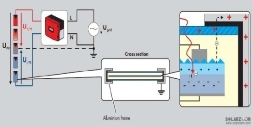
Figure (1) PID schematic
After the PID phenomenon occurs in the component, after the EL test, it can be generally seen that the phenomenon that the cell attenuates and darkens occurs first near the aluminum frame, because the voltage in these places is high. In addition, the component circuits adjacent to the input of the inverter are usually subjected to the maximum system voltage, so the components in these locations are also most likely to generate PID phenomena.
If the personnel designing the power station understand that the components within the power station may meet the above conditions, corresponding measures should be taken to prevent the components from generating PID. The measures that can be taken are: from the system side, it is possible to use the negative ground of the series components or to apply a positive voltage (for P-type silicon components) between the components that may cause PID phenomena and the ground in the evening. Another possible situation is that, as the micro-inverter is used, the system voltage is reduced and the resulting PID effect is negligible. The above three options will bring about additional equipment cost and efficiency decline. From the perspective of components and batteries, the use of different index of refraction at the battery end or double-layer anti-reflective passivation film and use of a high-resistivity film on the assembly side can effectively slow down the occurrence of PID phenomena.
The double glass module has no borders, and the component itself does not need to be grounded, so that in the case of moisture in the morning exposure of the double glass module, the area of ​​the clip spring or the hook connected to the bracket is small, and the impedance of the grounded bracket is much larger than that of the conventional components. , so its probability of generating PID is much smaller than that of conventional components.
2.2 The snails and cracks of the battery:
The generation of snail marks in the battery within the module is the combined result of multiple factors. However, the necessary condition is that the battery is cracked or the PN junction is exposed due to the battery etching process. Generally, a slight crack will not cause the output power of the battery and the module to drop. However, as the degree of cracking intensifies and the time passes, the effect of cracking on the attenuation of components will gradually appear. Severe cracking will inevitably lead to a decrease in the output power of the battery and the components, and even cause hot spots, until the components are burned. The battery is split between innate and acquired.
The EL test before leaving the factory is a key process to inspect the components that are inherently cracked. It can ensure that the components will not be cracked when they leave the factory. If there are components that do not affect the slight cracking of the electrical performance, they will be downgraded. Components with severe cracking will be Will be repaired and regraded. It is the responsibility of the component manufacturer to reject any cracks that may affect the electrical performance of the factory components.
Since each component has its own ID card - barcode, scanning bar code can get all the information of the component, including the production plant, the date of manufacture, the materials used, test data, EL image, etc., if you want to know whether the component is hidden from the factory Crack exists, simply notify the quality department of the production plant of the assembly and read the EL image at a glance.
There are many places where the possibility of component cracking will occur. The main reason is to follow the relevant rules in the process of transportation and installation. It is crucial to ensure that components are not subjected to human damage. If the battery is cracked at this stage, it is the responsibility of the transportation and installation party.
After the components are installed in place, the battery may still be cracked in the course of operation, maintenance, and cleaning. If human factors are involved, it is the responsibility of the operator. If the crack is caused by deformation of components such as wind and snow pressure, it is the responsibility of the power plant designer. If this risk is known, components with strong deformation resistance should be used, such as small-area components, thick glass, or with back support. Components and so on.
As for the snails, there must be a cracked battery in the snails. The author believes that the presence of cracked snails is not necessarily a bad thing. It reminds us to treat the components well. From the design and manufacture of components, the transportation of power plants and the installation of components to operation and maintenance must prevent the occurrence of battery cracks. In any case, cracking poses a serious threat to the long-term reliability of the component.
The double glass module has a natural anti-cracking performance. As long as the double glass component is used to ensure that the battery is not cracked at the time of shipment, there is almost no possibility of cracking.
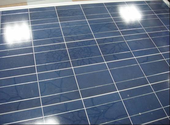
Figure (2) Snails
2.3 Hot Spots:
Component hot spots are generated in two situations:
1) Part of the shade of bird droppings, such as shadows, blocks the hot spots produced by the battery. At this time, it is only necessary to remove the covering.
2) The temperature of one or several batteries in the module is much higher than other batteries in the working state, indicating that these batteries are problem batteries, such as mixed low-grade batteries or batteries with small resistance and large leakage current, and long-term hot spots. At the same time, the aging of the packaging material is accelerated, and the battery decays faster and forms a vicious circle until the entire assembly is attenuated or scrapped. This type of defect should be the responsibility of the component manufacturer.
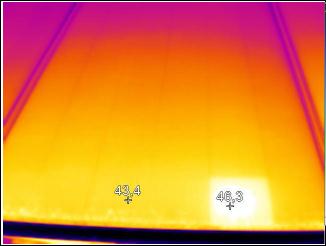
Figure (3) Hot Spot Assembly
2.4 Backplane Issues:
At present, there are a large variety of backplanes on the market. Selecting the right backplane is a required course for power plant designers. There are also many examples of component attenuation and scrap caused by backplane problems, such as cracking, delamination, bubbles, and yellowing of backplanes. Since there are certain differences in the aging of materials in different climatic regions, the design of the power station should select the most suitable backing material according to the climate characteristics of different regions. The problem of backplane caused by improper selection of backplane materials should be the responsibility of the plant designer. The designer of the power station selected suitable backplane materials. The backplane still has problems during the lifetime of the module and should be the responsibility of the component manufacturer.
To prevent cracking, bubbles, yellowing, and moisture vapor transmission in the backplane, double glass units are the best choice.
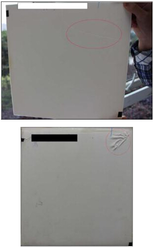
Figure (4) Backplate Shrinkage and Breakage
2.5 EVA issues
In the 80s of last century, foreign countries began to develop and produce EVA film, which has achieved satisfactory results in the solar cell package and outdoor use. At the beginning of this century, domestic EVA film is not mature, there is a serious yellowing, heat shrinkage and other issues, after the continuous efforts of domestic EVA film production enterprises, first, now our country has become the world's first production, high quality EVA film production of large countries There are more and more varieties, high penetration, high resistance, white reflective, wavelength conversion, anti-nail and other EVA film are very mature, so if the component EVA film has exceeded the standard requirements of bubbles, degumming, yellowing, etc. Problems should be the responsibility of the component manufacturer.
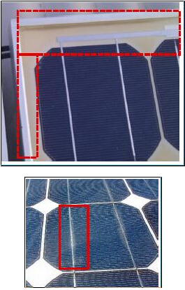
Figure (5) EVA yellow edge and delamination
2.6 welding problems
Welds of ribbons and cells, and welds of ribbons and ribbons, can result in a decrease in the output power of the module. In severe cases, sparking, burning through the backplane, or even a fire can occur. The responsibility is the component manufacturer.
2.7 Junction Box Problems
2.7.1
Welded joints in the junction box Weld-weld or Reed-type junction box The circlips are not clamped in the busbars. When the weight is less than the first one, the ignition may occur, the junction box may be burned, or even a fire may be caused. Such failure shall be caused by the assembly manufacturer. Be responsible for.
2.7.2
Bypass diodes burn for two reasons:
1) After the installation of the power station components is completed, the positive and negative poles of a series of components are reversed when wiring, and the large currents of other strings are instantaneously connected to the diodes in the reverse string box to burn the diodes, burn the junction box, and cause serious fires. This phenomenon should be the responsibility of the construction party of the power station;
2) The poor welding of diodes in the junction box, insufficient reverse voltage, and even the reverse polarity of the diodes may cause the diodes to burn out. This is the responsibility of the component manufacturer.
2.7.3
Water in the junction box may cause internal short-circuit, heat, and even burn. In severe cases, it may cause fire. The manufacturer of the module shall be responsible for removing the terminal box from cracking or damage due to improper operation.
2.8 Connector Problems
Possible problems with the connector of the module include: poor contact, excessive resistance, heat, fire, and even burning. If a problem arises due to improper connection, the power station installer is responsible for the problem. Problems such as incomplete soldering or poor contact with itself and excessive resistance should be the responsibility of the component manufacturer.
It is important to point out here that the connector of the power station may not be connected immediately after the component is installed, but it will be connected after a few days. At this time, the connector may be exposed outdoors, the connector may rain and water may enter, and the wind Sand, resulting in poor connector contact. In order to prevent such problems from occurring, the component manufacturer shall add a dust-proof, waterproof, sand-proof cap to the connector when the component is shipped from the factory, and close the socket end of the connector.
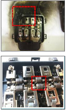
Figure (6) Junction box burned, diode failed
2.9 Glass Burst
Glass popping problems generally have two:
1) The self-explosion caused by the strong internal stress caused by the expansion of nickel sulfate in the glass itself, and the obvious "butterfly spot" at the point of explosion should be the responsibility of the component manufacturer;
2) When the construction party installs artificially and causes the component to burst, there will be obvious stress point at the explosion point. Such a problem shall be borne by the power station constructor. As shown in figure (7), the left picture is the explosion point, and the right picture is the explosion point caused by external force, which has obvious difference;
3) Problem The battery causes hot spot phenomenon of the component, and then the back plate is heated and burned. The large temperature difference locally may also cause the glass to burst. Such a problem should be borne by the component manufacturer.
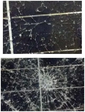
Figure (7) "Self-burst" and burst by external force
2.10 Natural disasters
We know that natural disasters are unavoidable. Lightning strikes, typhoons, etc. are mainly prevented by the designer, and earthquakes, mudslides, floods, tornados, and other force majeure depend on insurance.
Of course, there are some special circumstances, such as submerging the components after the water level rises. After the components are washed after the water is repelled, it will not affect the use. Cleaning the double glass components is much easier than the conventional components.
3. Conclusion
In summary, there are many reasons for abnormal attenuation and failure of components. The responsible parties involved mainly include component manufacturers, transportation and installation parties, operation and maintenance parties, and power plant designers. The author believes that only the separation of responsible parties will help solve the problem of abnormal attenuation and failure, extend the service life of components, and bring more benefits to investors.
Kn95 Surgical Mask,Kn95 Mask With Valve,Kn95 Certification Medical Mask,Kn95 Protective Surgical Mask
Ningbo Autrends Prevention Products Co., Ltd , https://www.autrendsafety.com